Take your first step towards the Career of your Dreams,

Discover Indovance Download our Brochure

Edit Template
Edit Template

Industry Info and CAD Tips

Compare AutoCAD vs Blender: Which is the best Modeling Software?

Computer-aided drafting (CAD) software is used by designers, illustrators, engineers and architects. The type of software one can best utilize depends on what kind of work will be done. One of the most recognized names in the CAD industry is AutoCAD. It has been around since the early 1980s. A younger contender, Blender, was developed about 10 years later. Let’s take a look at the differences between these two software programs and how their features are used by different types of designers. If you’re searching for an affordable CAD drafting company call Indovance today! Be sure to ask about how to qualify for a free project! AutoCAD vs Blender AutoCAD is somewhat of a base platform that can be built into whatever the designer needs based on the extensions and modifications that can be added to it. Those options give it a greater advantage to designers working with engineers and architects to create complex infrastructures that need information only AutoCAD can store such as cost estimations and simulation analysis. Simply put, AutoCAD is best for large-scale engineering or mechanical projects. Blender was created as an open-source project for 3D creation, including modeling, animation, composting, and even video editing and game creation. Because of its community-driven nature, it’s targeted at schools for educational purposes, students learning design, and hobbyists. Some consider it more of a tool for artists rather than developers. They even note on their website that their mission is to, “build a free and open-source complete 3D creation pipeline for artists and small teams.” When it comes to supported file types, the industry standard is the DWG series of formats. AutoCAD reads and writes these files as well as the interchange file format DXF. Blender has an internal file system that, while impressive in its ability to pack multiple files into a single one, isn’t widely recognized. However, Blender does support DXF as well as AVI and JPEG formats. Overall, Blender and AutoCAD don’t compare, but only because they aren’t made for the same purposes. An AutoCAD user is probably involved in architectural and mechanical designs, while a Blender user is probably working on something involving the design of a package, product, or even animation. The functions of AutoCAD, such as part assembly modeling, cost estimation, and documentation aren’t available in Blender. Other advanced AutoCAD features like construction modeling, surveying tools, and landscaping tools are also not available in Blender. AutoCAD offers training, but Blender does not. However, AutoCAD has a large learning curve so training is needed in order to master the software. Blender is easy to learn, and with its community of users available online, support can be found if it’s needed. Blender or CAD for your design needs?

What Are “As-Built Drawings” And Why Are They Important in Construction?

  There are various representations of facility documentation that can be specified during the facility life cycle. Design drawings depict the facility through the design process and thus reflect what it will become. They aid in the formation of consensus and the formulation of architectural and engineering decisions. Bid documents identify the facility to the point that a precise price can be calculated. The outcomes of the architect’s and engineers’ decisions, as well as their instructions to the contractor in the form of drawings and specifications, are illustrated in construction documents. Contractors or project managers create “as-built drawings,” which depict the facility as it was built and as it is supposed to be at the time of commissioning. Finally, Demolition drawings are used to illustrate the scope of work involved in deconstructing a building or sections of a building. All of these records can be categorized as facility documentation when taken together. What are as-built drawings? There may be some differences between the finished building and the drawings since both concept design drawings and shop drawings may go through several revisions. This is where as-built drawings come into play. As-built drawings are also known as record drawings, red-line drawings, and as-built plans. As-built drawings are representations of the facility’s current conditions. They depict the structure as it stands today, not as it was intended. Since buildings don’t always go according to plan, it’s a good idea to schedule as-built drawings even though you already have a collection of drawings. Nothing compares to a series of sketches that have been measured and field-checked. As-built drawing is a revised drawing that a contractor creates and submits after a construction project is completed. They include any revisions to the original sketches made during the design process, as well as an exact rendering of the building and property as it would look after completion. All items within the scope of the project should have their form, measurements, and specific positions detailed in as-built renderings. Any changes, whether minor or major, should be recorded, as well as a record of approvals for the changes. Also, minor information such as materials used should be registered if they vary from those specified in the original design, with planned but unused materials simply crossed out for future reference. Characteristics of As-Built Drawings As-built drawings are produced either before or after the design phase has been completed. It provides an indication of the actual project that was completed. To ensure that everybody looking at the plan understands the building activity, abbreviations are not used in as-built drawings. All variations in design, venue, materials, and so on are clarified in writing with the date, along with all changes from the original drawings. As-built sketches can be aided by photos and maps depicting the before and after of an activity, which can help to prevent potential misunderstandings. The adjustments made during the building process are noted in red ink on the original drawing, which can then be used to prepare as-built drawings. The adjustments made during the building process are noted in red ink on the original drawing, which can then be used to prepare as-built drawings. Fix the colour code, drawing size, and formats before preparing as-built drawings to ensure that the drawings are correct. For example, red represents deleted items, green represents added items, and blue represents special instructions and information. As-built drawings can be muddy due to inconsistency in identifying changes and alterations. The scale of the as-built drawing is close to that of the original drawing, allowing for easy comparison and comprehension. Where Are As-Built Drawings Used? Accurate and Detailed plans are critical for the success of any construction project. If the contractor encounters challenges with materials, the location, or governmental entities over the course of a project, the building’s features are likely to change. In particular, for commercial construction projects, as-built drawings are needed to document these changes and preserve an accurate image of the building as it currently exists. Here are some different applications of As-built drawings in Construction As-Builts for Success Before Construction Begins Connect with CAD Specialists Applications of As-built Drawings In Construction 1. New Construction Contractors will face various obstacles when constructing a new building that existed only on paper and will need to change their building plans in response. These as-built sketches document the changes as they occur during construction so that an accurate drawing of the building is available when it is finished. 2. Renovation/Remodelling It is important to have a thorough understanding of the current state of the building before embarking on a renovation project. As a result, for a safe and effective renovation, working with current drawings is critical. 3. Maintenance Small updates and modifications will be made over the life of a building. The construction staff of a building is responsible for updating as-built drawings to represent any improvements to the structure, ensuring that a correct drawing of the structure is available at all times. Why are As-Built Drawings Important? For various purposes, as-built sketches may be beneficial to all parties involved in a construction project. Having a full and accurate collection of as-built drawings is critical for clients and building owners. Since as-built drawings contain records of all installations, they are extremely useful if the owner wishes to change the building in the future or wants to troubleshoot issues. Contractors benefit from as-built drawings because they have a detailed record of improvements made during the construction process and make it easier to visualize the next steps. This makes it much easier to spot complications caused by the changes and solve them before they become a problem. As-built drawings are also an important part of the final sale since they are important to potential buyers of the land. They serve as a basis for any potential creation or changes and provide a simple testament to what is being sold and purchased. In general, as-built drawings are an essential component of any effective construction project. During design, modifications to

Importance of 3D Visualization & Animation in Modern Construction

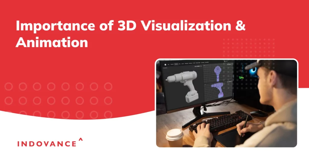
3D visualization has been an important discipline in the field of architecture as it enables architects and design planners to express their ideas and present them clearly and understandably. 3D Architectural animation can now offer onlookers a realistic image of a building even before the foundation stone is laid, all thanks to advancements in 3D animation technology. 3D modeling and animation technology is transforming the way we design in ways that were unimaginable many years ago. Architects and designers can now measure “proportions” and “scales” using intuitive interactive 3D modeling and simulate the effects of lighting, ventilation, and acoustics in internal environments using 3D rendering and architectural simulation software. What is 3D Animation and Visualization? The process of creating graphical content using 3D software is referred to as 3D visualization, 3D rendering, computer-generated imagery (CGI), 3D graphics, and other similar terms. Transforming 2D drawings into reality, 3D animation and visualization provide a three-dimensional view with real-world effects that the 2D effect did not provide. It can handle designs in real-time, quickly transition from concept to concrete and explore various options, refinements and multiple design versions. 3D visualization, modeling, and animations aid design the building or structure in the way it seems to be in real-time. Customers can experience and visit the building virtually before building it, while architects and engineers can gain a better understanding of each floor, critical areas, landscape, textures, heights, etc. This visual model keeps all the stakeholders on the same page and enables smooth flow of construction processes and operations. Visualize your Dream Design

What Is Value Engineering in Construction

Companies in the construction sector tend to lose a lot of time and money on expensive and unnecessary building materials or structures that are non-essential for the intended function of the building. Discover how Value Engineering can be applied to your construction projects to overcome these challenges. VE (value engineering) evolved at the General Electric Corp. during World War II is a calculated and precise set of disciplined procedures designed to seek out the best value for both initial and long-term investment. The Society of American Value Engineers International (SAVE International) defines Value analysis as a “structured approach to analyze and improve manufacturing products and processes, design & construction projects, and business & administrative processes.” Although Value Engineering can be applied at any point in a project however it should be typically performed as early as possible—before engagement of funds approval of systems, services, or design to maximize return on time and money invested. The figure below represents the study that shows the maximum benefits of Value Engineering in the initial or conceptual phase. The Stages of Value Engineering 1. Planning Stage: The planning stage is the earliest or conceptual phase of project development therefore it is utmost important to maintain clear & crisp communication for your construction projects. Begin your project with a detailed plan so that there are fewer changes and redesigns down the line that could affect the overall schedule, cost and design plans. HOW? Define key goals, standards, and guidelines for your project Functional analysis of the facility Review of all utility and material options Projecting a well-defined budget for your project Explore the Concept of alternative and sustainable solutions – Often the answer lies in working with an experienced and trusted Outsourcing Partner which can provide quick TAT (Turnaround time on various conceptual designs for layout comparison. This will further expedite the process of quickly visualizing and examining alternate designs. 2. Design Stage: This is the stage where the conceptual design has at least made it to the schematic stage. This gives the opportunity to bring the design team and client together to evaluate the proposed design solutions, the cost estimate, and proposed implementation schedule and approach, to implement the best value for the money. However, this definition of what is good value on any particular project will change from client to client and project to project.  3. Value Engineering Process or Value Engineering Methodology: Value Engineering Process is the last and final stage which is broken up into six important steps. 6 Stages of Value Engineering Process or Value Engineering Methodology 1. Information gathering: The information phase is aimed at gathering all data needed to understand the full scope of the project. HOW? Understand the framework and decisions that have influenced the development of the design through a formal design presentation. Analyze the key functional issues governing the project. The functions of any facility or system are the controlling elements in the overall VE approach. This procedure demands the participants to think in terms of function, and the cost and impacts associated with that function. Define Owner’s objectives and key criteria governing the project. Determine Owner’s definition of Value. 2. Function Analysis: The primary function is the essence of the project which requires you to determine what is required to make the project work. 3. Creative Speculation: Generate ideas on all the possible ways to accomplish the required  HOW?  Define the guidelines to be used for evaluation Examine and assess the plans resulting from the creative session. Ideas found to be impractical or ineffective rejected. Those designs that represent the greatest potential for cost savings and value addition are developed further. E.g. (schedule impacts, aesthetics, etc.). 5. Development: Establish ideas into a written and verbal proposal that will be presented in the final stage of the project. HOW? Description of the approved design changes. A detailed evaluation of the benefits and limitations of the proposed design. Value comparison and LCC (life-cycle cost) calculations. Compare the original design method to the proposed change. 6. Presentation: The purpose of this stage is to obtain approval for the project. Present your proposal to all stakeholders and decision-makers and explore any final possible alternatives before moving forward to the Construction phase. HOW? Clarify project objectives. Identify and prioritize Client’s value objectives. Implement admitted plans into design. Provide a feedback. Read More: Value Engineering in MEP Coordination The Value-Conscious options of Outsourced Delivery Outsourcing engineering services contain an inherent added value over in-house design/drafting processes. Commencing from an early phase of conceptual design process to the final design delivery, multiple benefits as associated which contribute to economic planning, design, and construction phases.  Option 1 – Multiple Engineering & Construction projects comprise of large volume of repetitive tasks particularly in Structural, Mechanical and Civil/Land Surveying projects. Outsourcing these projects not only saves you on cost but also provides a competitive edge with quicker TAT (Turnaround time). Also giving engineering firms the option to focus on their Core Competencies and Client management. Option 2 – Then there are numerous projects which demand highly specialized skill sets. Incorporating technology changes every time incurs high investment costs in procuring the software and hiring/training in-house. Many engineering firms have resonated on the dearth of skilled resources leading to loss of projects. Outsourcing brings out the maximum value in these kind of projects at Zero setup cost. Tools like REVIT, MICROSTATION, are some of the predominantly outsourced services. INDOVANCE Value Offering Cost Benefit – Reduce O&M (Operation & Maintenance) costs up to 54% ISO Certified – Process driven approach for quality management and error free delivery. Transparency – Full control over dedicated resource and project deadlines. Communication – Proactive approach to identify & mitigate issues and ensure smooth workflow. Experience – 17+ years of Industry experience in diverse engineering & construction projects. Competitive Edge – Empowering C-Level Executives to focus on Core Competencies.   The purpose of Value engineering in construction is not just reducing the costs, increasing the design standards, making it easier to build the project and saving time and

BIM Versus AutoCAD(D) – What’s the Difference?

  While today we live in an era of technological advancement, there were times that the design and drafting need to be hand-drawn throughout the project life cycle. It was a tedious task but had no other way around. But with today’s software catering to the needs of the professionals, AutoCAD and BIM are few of the most used and widely popular amongst the construction and design industry professionals. So what is CAD(D) exactly? CAD stands for computer-aided design. You can also add an extra D for drafting as well. It is used for design development and optimizing your work. It enables the professionals to design on their computer screen and save it for editing in the future. It is used for preliminary designing, layout, detailing work and also calculations. You can also make a 3D representation of the object in CAD(D). Professionals whom it caters to – 1. Engineers 2.Architects 3.Designers With CAD in the background, the professionals are freaking out over BIM and the easy workflow that it offers. So, what is the hype over BIM? Well, the hype is real and for some real reasons! Unlike CAD being software, BIM is a process through which generating drawings are much easier and faster. Here is an illustration explaining the many facets of BIM  It facilitates all the important aspects of designing in the form of digital representation. Not just geometrical, it covers everything from a spatial relationship, light analysis, geographical form, etc. Professionals whom it caters to – 1.Engineers 2.Architects 3.Designers 4.Constructors 5.Business Owners Still, confused? CAD is the software dedicated in design and drafting works, whereas BIM is a process, a methodology by which professionals can work collaboratively to design and build a building, establishing the same details use and computer model. This allows for easier communication and breaks the barriers of time and distance. It does so by acting as a common resource working across multiple disciplines of designing and drafting. Since both differ in usages, it completely depends on the professionals as to what kind of outcomes they are expecting. As far as CAD is concerned it is typically used for the industrial design of mechanical and electrical. Whereas, BIM is extensively used in the design and construction industry. How Indovance can help you gain expertise in your business Indovance caters in CAD drafting and modelling and BIM services since 2003. We majorly work in Mechanical, Architecture, Civil, Graphics and Pre-media domain and can put all your worries at bay. With a team of experts, we can help you and your team in performing better and faster than your competition. You can outsource you CAD Design and Modeling and BIM services and we assure to you guaranteed quality results with the quickest TAT possible. You can email us at info@indovance.com and can log in to our website www.indovance.com to know more about our services and our work portfolio.

Indovance partnered to develop Solar Panel project on 314 Acres of Land!

Did you know the energy, the Sun provides for one hour is enough to generate electricity for a complete year globally? However, we are not using even a fraction of it to our benefit. Harnessing solar power can bring in a very significant change to our ecosystem. But all these boils down to just one thing. Who will make it possible? One of the companies in the USA took up a work of setting up large solar panels on a gigantic area of land. They needed assistance for the project planning and drafting through CAD software where Indovance partnered with them to complete the project in time. Here is how Indovance helped setting up 3500 Solar Panels on a land as huge as 314 acres! Client Overview Our client, a leading solar equipment company based in the USA, deals in installations of solar panels. They were looking for an outsourcing partner to help them in managing all the software related work for solar installation such as Drafting, Proposing Site, Layouts, Contour Mapping, etc. The client liked the project management cycle that we follow and was quick enough to become a long-term business partner so that any sudden spike at work does not make any harm to the ongoing work process and still get the work delivered on time. Our client was a leading solar equipment company from the USA.  Client Input We received data in a pdf format where the existing site conditions, such as property boundary, wetland area and contour levels were shown for quick reference. All the work needed to be done keeping in mind the given inputs in Civil3D software. Client Requirement Client wanted us to prepare a Construction Document Set (A set of production drawings). Which will include a Site plan, Grading plan, Layout plan and the Existing site condition plan. Challenges Observed Since the project had some very strict standard guidelines and were high on deadlines, we built a team of members who already had expertise and experience in working on such projects. This made us save a huge amount of time on training hours. Also, a backup resources were deployed to accommodate any additional deliverables. Moreover, team had to be abreast with the US construction code and standards. Indovance Solution Architect We made all the sheet with the expected details that were required. A total of 3 main files and their multiple sub-files were created for the clarity in understanding and execution of work. Existing Condition – All existing conditions giving under the civil base plan. This includes all the natural and man-made features already present on-site such as contours, stream, pond, trees etc. Tree Clearance – Herein, all the unnecessary trees had to be cut to propose solar panels and show proper fence line for security purpose and Calculation of the area. Layout and Material – Proper site layout need to be done here, by calculating the site distances from all sides according to the standards mentioned and put all the callouts and utility poles wherever necessary. Grading and Erosion control – Propose contours if needed for a conducive environment. Place the electrical equipment area, utility poles and other solar panel details. Also, propose Stilt fencing for erosion control for not damaging the existing condition. Value Added Indovance provided excellent quality-infused work with all the necessary parameters checked and also completed the project in stipulated time. Also, Outsourcing CAD services to Indovance helped our partner in reducing the overall cost of project. All of these became possible because of the 3-stage quality process that enabled us to make the project get delivered with minimum to zero errors. This significantly reduced the rework time as well. Indovance has a prolific work experience in CAD Drafting and Modelling services since its inception in 2003. We choose to deliver output which are designed uniquely keeping our client’s requirement in mind. We cater to services majorly in the domain of Mechanical, Architecture, Civil, Graphics and Pre-Media. For any work related queries, e-mail us at info@indovance.com. You can also log on to our        website www.indovance.com for better understanding our work portfolio.

© 2024 Indovance. All Rights Reserved.

Scroll to Top